| | GDS-3152 | GDS-3154 | GDS-3252 | GDS-3254 | GDS-3352 | GDS-3354 |
| Vertical |
| Input Channels | 2Ch+EXT | 4Ch+EXT | 2Ch+EXT | 4Ch+EXT | 2Ch+EXT | 4Ch+EXT |
| Bandwidth | DC~150MHz(-3dB) | DC~250MHz(-3dB) | DC~350MHz(-3dB) |
| Rise Time | 2.3ns | 1.4ns | 1ns |
| Vertical Resolution | 8 bits |
| Vertical Resolution@ 1MΩ | 2mV~5V/div |
| Vertical Resolution@ 50/75Ω | 2mV~1V/div |
| Input Coupling | AC, DC, GND |
| Input Impedance | 1MΩ// 16pF |
| DC Gain Accuracy | ±(3% X |reading| + 0.1div+ 1mV) |
| Polarity | Normal and inverted |
| Maximum Input Impedance @1MΩ | 300V (DC+AC peak), CAT I |
| Maximum Input Impedance @50/75Ω | 5 Vrms ,CAT I |
| OffsetPositionRange | 2mV/div ~ 100mV/div: ±0.5V
200mV/div ~ 5V/div: ±25V |
| Bandwidth Limit | 20MHz (-3dB) | 100MHz (-3dB) | 200MHz (-3dB) |
| Waveform Signal Processing | Addition, Subtraction, multiplication, division, FFT, FFTrms |
| Trigger |
| Source | Dual channel: CH1, CH2, Line, Ext ; 4 channel: CH1, CH2, CH3, CH4, Line, Ext |
| Trigger Mode | Auto (Auto (supports Roll Mode for 100 ms/div and slower), Normal, Single |
| Trigger Type | Edge, Pulse Width, Video, Runt, Rise & Fall, Alternative, Event-Delay (1~65,535) events, Time-Delay(10nS~10S), I2C, SPI, UART |
| TriggerHold-off Range | 10ns~10s |
| Coupling | AC, DC, LF rej, HF rej, Noise rej |
| Sensitivity | DC~50MHz approx. 1div or 1.0mV
50MHz~150MHz approx. 1.5div or 15mV
150MHz~350MHz approx. 2div or 20mV |
| EXT Trigger |
| Range | ±15V |
| Sensitivity | DC~150MHz approx.100mV
150MHz~250MHz approx. 150mV
250MHz~350MHz approx. 150mV |
| Input Impedance | 1MΩ±3%, ~16pF |
| Horizontal |
| Range | 1ns/div~100s/div (1-2-5steps); ROLL: 100ms/div~100s/div |
| Pre-Trigger | 10div maximum |
| Post-Trigger | 1,000div |
| Accuracy | ±20 ppm over any ≧1 ms time interval |
| Signal Acquisition System |
| Real Time Sample Rate | 2.5GSa/s | 5GSa/s | 2.5GSa/s | 5GSa/s | 5GSa/s | 5GSa/s |
| Equivalent Time Sample Rate | 100GSa/s maximum for all models |
| Record Length | 25k points |
| Acquisition Mode | Normal, Average, Peak Detect, High resolution, Single |
| | Normal: Acquire sampled values |
| | Average: From 2 to 256 waveforms included in average |
| | Peak Detect: Catches glitches as narrow as 2ns at all sweep speeds |
| | Hi Res: Real-time boxcar averaging reduces random noise and increases vertical resolution |
| X-Y Mode |
| X-axis input | Channel 1; Channel 3 |
| Y-axis input | Channel 2; Channel 4 |
| Phase Shift | ±3° at 100kHz |
| Cursors and Measurement |
| Cursors | Amplitude, Time, Gating available |
| Automatic Measurement | 28 sets: Vpp, Vamp, Vavg, Vrms, Vhi, Vlo, Vmax, Vmin, Rise Preshoot/ Overshoot, Fall Preshoot/Overshoot, Freq, Period, Rise Time, Fall Time, Positive Width, Negative Width, Duty Cycle, Phase, eight different delay measurements (FRR, FRF, FFR, FFF, LRR, LRF, LFR, LFF) |
| Cursors Measurement | ∆V, ∆T |
| Auto Counter | 6digits, range from 2Hz minimum to the rated bandwidth |
| Power Measurements (optional) |
| Power Quality Measurements | VRMS, V Crest Factor, Frequency, IRMS, I Crest Factor, True Power, Apparent Power, Reactive Power, Power Factor, Phase Angle. |
| Harmonics | Freq, Mag, Mag rms, Phase, THD-F, THD-R, RMS |
| Ripple Measurements | Vripple, Iripple |
| In-rush Current | First peak, second peak |
| Control Panel Functions |
| Autoset | Single-button, automatic setup of all channels for vertical, horizontal and trigger systems, with undo autoset |
| Auto-Range | Allows users to quickly move from test point to test point without having to reset the oscilloscope for each test point |
| Save Setup | 20 sets |
| Save Waveform | 24 sets |
| Display System |
| TFT LCD | 8" TFT LCD SVGA color display (LED backlight) |
| Display Resolution | 800 horizontal × 600 vertical (SVGA) |
| Interpolation | Sin(x)/x and equivalent time sampling |
| Waveform Display | Dots, Vectors, Variable persistence, infinite persistence |
| Display Graticule | 8 x 10 divisions |
| Display Brightness | Adjustable |
| Interface |
| RS-232C port | DB-9port |
| USB port | 2 sets USB 2.0 high-speed host port; 1setUSB 2.0 high speed device port |
| Ethernet | RJ-45 port, 10/100Mbps |
| VGAVideoPort | DB-15port, SVGA monitor output |
| Line Output | 3.5mm stereo output jack for Go/NoGo audio alarm |
| GPIB(Optional) | USB to GPIB converter |
| Go/NoGo BNC | Maximum 5V /10mA TTL open collector ouput |
| Kensington Style Lock | Rear panel security slot connects to standard Kensington style lock |
| Power Source |
| LineVoltageRange | AC 100V ~ 240V, 48Hz ~ 63Hz, Auto selection |
| Miscellaneous |
| Multi-language Menu | Available |
| On-line Help | Available |
| Time clock | Time and Data ,Provide the Data/Time for saved data |
| Dimensions and Weight | 400(W) x 200(H) x 130(D), approx. 4 kg. |
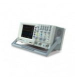
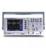
 Digital Oscilloscope


 View full size