


No products in the cart.


Data Acquisition (DAQ)
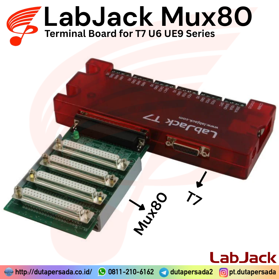
LabJack Mux80 – AIN Expansion Board for T7 U6 UE9 Series
Availability:
5 in stock
Analog input expansion board that adds 80 analog input channels. It can be connected to a U6/Pro, UE9, or T7/Pro directly through the DB37 connector. Ten of the LabJack’s analog inputs are multiplexed (1:8 each) by the Mux80, and 4 are left untouched on AIN0-3 screw terminals, bringing the total number of available analog inputs to 84.
Status Barang: Ready
Kondisi: Baru
Minimal Order: 1 pcs
OVERVIEW: Analog input expansion board that adds 80 analog input channels. It can be connected to a U6, UE9, or T7 directly through the DB37 connector. Ten of the LabJack’s analog inputs are multiplexed (1:8 each) by the Mux80, and 4 are left untouched on AIN0-3 screw terminals, bringing the total number of available analog inputs to 84.
FEATURES:
◆ 80 channels
◆ OEM capability
◆ High density connectors
◆ Snaptrack/DIN rail compatible
Compatible Products:
◆ T7 Series
◆ U6 Series
◆ UE9 Series
EACH UNIT INCLUDES WITH:
◆ Mux80
◆ Screwdriver
| Weight | 0.5 kg |
|---|
The Mux80 AIN Expansion Board serves to provide an additional 80 analog inputs to any compatible LabJack. It uses 10 multiplexer chips connected to AIN4-AIN13 and splits each channel into 8 additional channels. When a specific extended analog input channel is read on a U6/Pro, UE9, or T7/Pro, the digital output MIO lines are automatically set and the correct analog channel is read. The Mux80 has a built-in DC-DC converter which provides the upper and lower rail voltages necessary for powering the multiplexer chips.
Three vertical DB37 connectors provide an easy interface to connect 24 AIN channels each. The remaining connector brings out unused connections (FIO, DAC, etc) from the LabJack, along with the last 8 AIN channels. There are a total of 84 available analog inputs when used in conjunction with a U6/Pro, UE9, or T7/Pro.
For screw-terminal access, connect a CB37 Terminal Board and reference the chart printed at the top of the Mux80 for connections.
Subsections
Features
- 80 Multiplexed Channels (or 40 Differential Pairs)
- Built-In DC-DC Converter
- OEM Capability
- Easy-To-Use High Density Connectors
- Snaptrack/DIN-rail compatible, with TE Connectivity P/N TKAD

Connection Options
The Mux80 can be connected several ways. The images below demonstrate use with the CB37 Terminal Board, and several 3ft DB37 Cables.


When connected to a CB37, there is a quick way to determine which screw terminals can be used as analog inputs; reference the chart printed on the top of the Mux80, also shown below for reference.
Table 1. CB37 to MUX80 connection chart
| AIN13 | N/C | AIN61 (53N) | AIN85 | AIN109 (101N) |
| AIN12 | N/C | AIN60 (52N) | AIN84 | AIN108 (100N) |
| AIN11 | AIN127 (119N) | AIN59 (51N) | AIN83 | AIN107 (99N) |
| AIN10 | AIN126 (118N) | AIN58 (50N) | AIN82 | AIN106 (98N) |
| AIN9 | AIN125 (117N) | AIN57 (49N) | AIN81 | AIN105 (97N) |
| AIN8 | AIN124 (116N) | AIN56 (48N) | AIN80 | AIN104 (96N) |
| AIN7 | AIN123 (115N) | AIN55 | AIN79 (71N) | AIN103 |
| AIN6 | AIN122 (114N) | AIN54 | AIN78 (70N) | AIN102 |
| AIN5 | AIN121 (113N) | AIN53 | AIN77 (69N) | AIN101 |
| AIN4 | AIN120 (112N) | AIN52 | AIN76 (68N) | AIN100 |
| AIN3 | AIN3 (2N) | AIN51 | AIN75 (67N) | AIN99 |
| AIN2 | AIN2 | AIN50 | AIN74 (66N) | AIN98 |
| AIN1 | AIN1 (0N) | AIN49 | AIN73 (65N) | AIN97 |
| AIN0 | AIN0 | AIN48 | AIN72 (64N) | AIN96 |
| MIO0 | MIO0 | N/C | N/C | N/C |
| MIO1 | MIO1 | N/C | N/C | N/C |
| MIO2 | MIO2 | N/C | N/C | N/C |
| PIN2 | PIN2 | N/C | N/C | N/C |
| PIN20 | PIN20 | N/C | N/C | N/C |
| FIO7 | FIO7 | AIN71* | AIN95 (87N) | AIN119* |
| FIO6 | FIO6 | AIN70* | AIN94 (86N) | AIN118* |
| FIO5 | FIO5 | AIN69* | AIN93 (85N) | AIN117* |
| FIO4 | FIO4 | AIN68* | AIN92 (84N) | AIN116* |
| FIO3 | FIO3 | AIN67* | AIN91 (83N) | AIN115* |
| FIO2 | FIO2 | AIN66* | AIN90 (82N) | AIN114* |
| FIO1 | FIO1 | AIN65* | AIN89 (81N) | AIN113* |
| FIO0 | FIO0 | AIN64* | AIN88 (80N) | AIN112* |
| DAC1 | DAC1 | AIN63 (55N) | AIN87 | AIN111 (103N) |
| DAC0 | DAC0 | AIN62 (54N) | AIN86 | AIN110 (102N) |
*: When taking differential measurements, the negative channel that goes with this positive channel is on a different X# connector.
(##N): When taking differential measurements, this denotes the positive channel that goes with this negative channel. For example, “AIN56 (48N)” indicates that AIN48 is the positive channel that goes with the negative channel AIN56. In other words, 48N means “AIN48’s negative”.
The table above defines the pinouts of X2-X5 in terms of a CB37. If you are not using a CB37, see the CB37 Datasheet to translate the CB37 terminals to DB37 pin numbers and/or Appendix A.
X2
Connector X2 is essentially a duplicate of the DB37 connector on the main device, except AIN4-AIN11 are instead AIN120-AIN127, and AIN12-AIN13 are not connected to anything. On connector X2, AIN0-AIN3 are duplicates of the main device, as well as FIO, DAC, etc.
AIN0-AIN3 are available on the built-in terminals of the T7 and also on AIN0-AIN3 of a CB37 connected to X2.
AIN120-AIN127 are available on X2, along with the DACs and DIO.
X3
AIN48-AIN71 appear on the AIN0 through FIO7 terminals of a CB37 connected to X3. Note that terminals labeled DACx and FIOx on the CB37 are used as analog inputs.
X4
AIN72-AIN95 appear on the AIN0 through FIO7 terminals of a CB37 connected to X4. Note that terminals labeled DACx and FIOx on the CB37 are used as analog inputs.
X5
AIN96-AIN119 appear on the AIN0 through FIO7 terminals of a CB37 connected to X5. Note that terminals labeled DACx and FIOx on the CB37 are used as analog inputs.
Example
A signal is connected to FIO6 on a CB37. The CB37 is connected to X4 on the Mux80, so on the chart, under X4 and FIO0-7, locate AIN88-95. So the signal is connected to AIN94. To read AIN94 simply perform a standard AIN read for analog input number 94.
Using Differential Analog Inputs with the MUX80
Built-in
The built-in analog inputs AIN0 through AIN3 can be used normally when using the Mux80 (but AIN4 through AIN13 are not available). This allows:
- Positive channel = AIN0 paired with negative channel = AIN1
- Positive channel = AIN2 paired with negative channel = AIN3
Extended Range
For extended channels, the positive channel can be any channel (even or odd) listed as a positive channel in the chart below. The negative channel number is the positive channel number plus 8 (listed under the “Negative Channel” the chart below).
Example 1: The positive channel is connected to AIN102 (AIN6 on the CB37 connected to X5). The corresponding negative channel is AIN110 (DAC0 on the CB37 connected to X5).
Example 2: The positive channel is connected to AIN64 (FIO0 on the CB37 connected to X3). The corresponding negative channel is AIN72 (AIN0 on the CB37 connected to X4).
Note that for some differential pairs, the positive and negative are located on different connectors.
Table 2. Channel numbers for analog inputs based on differential connection and CB37 connector
| X2 | |||
| Positive Channel | Negative Channel | ||
| CB37 Label | AIN# | CB37 Label | AIN# |
| X2’s AIN0 | AIN0 | X2’s AIN1 | AIN1 |
| X2’s AIN2 | AIN2 | X2’s AIN3 | AIN3 |
| X3 | |||
| Positive Channel | Negative Channel | ||
| CB37 Label | AIN# | CB37 Label | AIN# |
| X3’s AIN0 | AIN48 | X3’s AIN8 | AIN56 |
| X3’s AIN1 | AIN49 | X3’s AIN9 | AIN57 |
| X3’s AIN2 | AIN50 | X3’s AIN10 | AIN58 |
| X3’s AIN3 | AIN51 | X3’s AIN11 | AIN59 |
| X3’s AIN4 | AIN52 | X3’s AIN12 | AIN60 |
| X3’s AIN5 | AIN53 | X3’s AIN13 | AIN61 |
| X3’s AIN6 | AIN54 | X3’s DAC0 | AIN62 |
| X3’s AIN7 | AIN55 | X3’s DAC1 | AIN63 |
| X3 & X4 | |||
| Positive Channel | Negative Channel | ||
| CB37 Label | AIN# | CB37 Label | AIN# |
| X3’s FIO0 | AIN64 | X4’s AIN0 | AIN72 |
| X3’s FIO1 | AIN65 | X4’s AIN1 | AIN73 |
| X3’s FIO2 | AIN66 | X4’s AIN2 | AIN74 |
| X3’s FIO3 | AIN67 | X4’s AIN3 | AIN75 |
| X3’s FIO4 | AIN68 | X4’s AIN4 | AIN76 |
| X3’s FIO5 | AIN69 | X4’s AIN5 | AIN77 |
| X3’s FIO6 | AIN70 | X4’s AIN6 | AIN78 |
| X3’s FIO7 | AIN71 | X4’s AIN7 | AIN79 |
| X4 | |||
| Positive Channel | Negative Channel | ||
| CB37 Label | AIN# | CB37 Label | AIN# |
| X4’s AIN8 | AIN80 | X4’s FIO0 | AIN88 |
| X4’s AIN9 | AIN81 | X4’s FIO1 | AIN89 |
| X4’s AIN10 | AIN82 | X4’s FIO2 | AIN90 |
| X4’s AIN11 | AIN83 | X4’s FIO3 | AIN91 |
| X4’s AIN12 | AIN84 | X4’s FIO4 | AIN92 |
| X4’s AIN13 | AIN85 | X4’s FIO5 | AIN93 |
| X4’s DAC0 | AIN86 | X4’s FIO6 | AIN94 |
| X4’s DAC1 | AIN87 | X4’s FIO7 | AIN95 |
| X5 | |||
| Positive Channel | Negative Channel | ||
| CB37 Label | AIN# | CB37 Label | AIN# |
| X5’s AIN0 | AIN96 | X5’s AIN8 | AIN104 |
| X5’s AIN1 | AIN97 | X5’s AIN9 | AIN105 |
| X5’s AIN2 | AIN98 | X5’s AIN10 | AIN106 |
| X5’s AIN3 | AIN99 | X5’s AIN11 | AIN107 |
| X5’s AIN4 | AIN100 | X5’s AIN12 | AIN108 |
| X5’s AIN5 | AIN101 | X5’s AIN13 | AIN109 |
| X5’s AIN6 | AIN102 | X5’s DAC0 | AIN110 |
| X5’s AIN7 | AIN103 | X5’s DAC1 | AIN111 |
| X5 & X2 | |||
| Positive Channel | Negative Channel | ||
| CB37 Label | AIN# | CB37 Label | AIN# |
| X5’s FIO0 | AIN112 | X2’s AIN4 | AIN120 |
| X5’s FIO1 | AIN113 | X2’s AIN5 | AIN121 |
| X5’s FIO2 | AIN114 | X2’s AIN6 | AIN122 |
| X5’s FIO3 | AIN115 | X2’s AIN7 | AIN123 |
| X5’s FIO4 | AIN116 | X2’s AIN8 | AIN124 |
| X5’s FIO5 | AIN117 | X2’s AIN9 | AIN125 |
| X5’s FIO6 | AIN118 | X2’s AIN10 | AIN126 |
| X5’s FIO7 | AIN119 | X2’s AIN11 | AIN127 |
Specifications
| Parameter | Conditions | Min | Typical | Max | Units |
| Typical Current Draw | No Active Readings | 4.5 | 5.5 | 10 | mA |
| VMUX+ | 12.8 | 13.8 | 16 | V | |
| VMUX- | -12.8 | -13.8 | -16 | V | |
| Crosstalk @ 100 Hz | DG408DVZ | -125 | dB | ||
| LabJack U6 | -104 | dB | |||
| Mux80 | -100 | dB |
Ground Offsets
A single-ended analog input measurement is the voltage difference between the analog input and ground at the A/D chip on the main device (e.g. U6/Pro or T7/Pro). If the voltage provided by a given signal is different than the voltage at the A/D chip, that results in error.
Suppose, for example, a thermocouple is connected to AIN0 and the adjacent GND terminal on a CB37, that is connected to X3 on a Mux80 via a 3 foot cable, and that is connected to a T7. Suppose the remote end of thermocouple is at a temperature such that it is creating a voltage difference of 1600 µV between the AIN0 and GND terminals on the CB37. Typically, the voltage at the CB37-AIN0 terminal will be the same voltage presented to the A/D chip, but the voltage at the CB37-GND terminal might be 280 µV higher than ground at the A/D chip due to other currents flowing on ground. That means the A/D chip will see 1880 µV rather than 1600 µV, which is an error of roughly 7 degrees C.
Voltage drop on the AIN connection is not a concern as the only current on the AIN connection is the bias current. The typical AIN bias current of the U6/Pro or T7/Pro is 20 nA, so even if the path from terminal to A/D chip had a high resistance of 10 ohms that would only be 200 nV of error.
Voltage drop on the ground connection can sometimes be a concern and is called ground offset error. Just the normal power supply current of the Mux80 and CB37 can cause GND terminals on the CB37 to be 100s of microvolts higher than ground back at the A/D chip. Any current sunk to GND by user connections will increase this difference.
One solution is to use the AGND terminal on the CB37. AGND has its own dedicated path back to the main device, so as long as the user does not sink any current into AGND it will be at the same voltage as ground at the A/D chip.
To measure how much offset exists from a particular GND terminal to ground at the A/D chip, simply jumper the GND terminal in question to an unused AIN terminal and measure the single-ended voltage from that AIN channel.
Suggestions & Solutions:
A. Use differential analog inputs. Differential readings take the difference between 2 AIN lines and thus are not affected by ground offset. For example with a thermocouple, connect thermocouple+ to a positive channel (AIN48 for example) and connect thermocouple- to a negative channel (AIN56 for example). A resistor (100k would be typical e.g. CF14JT100K) from the negative channel to GND is also required, as the thermocouple cannot be totally floating (see the Differential Readings App Note). Now configure and read AIN48 as differential.
B. Use AGND for all passive sensors such as thermocouples. Make sure not to connect anything to AGND that will sink/source any substantial current to AGND or offset will be created from AGND versus A/D chip ground.
C. Use an extra AIN channel on the CB37 in question and jumper it to GND on the CB37 to measure the GND offset so it can be accounted for in software.
D. Get rid of or at least reduce GND offset by minimizing connections (minimizing resistance) between the signal terminals and A/D chip, avoiding sourcing/sinking current to GND on the CB37, and adding a big fat wire from CB37-GND to U6-GND or T7-GND.
E. Use a star ground, and have a single solid connection from that star ground to U6-GND or T7-GND. For example, connect the negative leads of all signals to an external grounding post or grounding bar, and run a big fat wire from there to a GND on the main LabJack.
Software
The Mux80’s extended channels (AIN48-AIN127) act just like normal channels (AIN0-AIN13) and are read the same way. For example, one of the T7’s built-in analog inputs can be sampled by reading “AIN0”. To sample an analog input on the Mux80, you can read “AIN48”. Similarly, AIN configurations like range and resolution are configured in the same way for extended channels as they are for normal channels. Configurations that apply to ALL channels do include normal and extended.
Some LabJack logging programs can only log data from 16 channels at a time. In these cases, custom or third party software may be necessary to log more than 16 MUX80 AIN channels. See the software options page for your device for more detailed information about available logging programs.
Troubleshooting
MIO0-2 are used to control the MUX80 multiplexers; ensure the MIO are not being used as normal DIO while trying to take readings from the MUX80.
For initial testing, the same steps that are described in our Test an AIN application note can be performed. With T-series devices, the extended AIN registers (whose hardware mapping is described in Table 1, Table 2, and on the pinout page) can be read directly in Kipling using the register matrix tab. For UD devices, see the “U6 or UE9 only” guide below.
If there seem to be problems with incorrect readings, also check that VMUX+ and VMUX- are within specified limits by measuring the test points with respect to GND. The Mux80 does not use VM+/VM- from the main device at all, but rather has its own power supply circuit to convert 5V (VS) to ±13V (VMUX+ and VMUX-) for the mux chips. Note that with a CB37 connected to any of X2-X5, the screw terminals labeled VM+/VM- are actually connected to VMUX+ and VMUX-, so this is a another way to measure besides the test points on the PCB.
Troubleshooting – U6/Pro or UE9 Only
It is possible to check Mux80 functionality in LJControlPanel by performing the following steps:
- Open LJControlPanel
- Select UD device and click Test
- On test pane, locate MIO 00, MIO 01, MIO 02 checkboxes for both Digital Direction and Digital State
- Check the boxes for all 3 MIO lines under Digital Direction
- Check desired boxes under Digital State according to the following table. Find the extended channel number to investigate, then trace across the row to the Digital State of MIO0, MIO1, and MIO2. Set the output state to high (checked) for 1 and low (un-checked) for 0.
- Trace the column up to AIN#, this is the analog input that your analog signal will appear on.
Table 3. Channel selection based on mux input
| Output State | Expected Channel in LJControlPanel | ||||||||||||
| MIO0 | MIO1 | MIO2 | AIN4 | AIN5 | AIN6 | AIN7 | AIN8 | AIN9 | AIN10 | AIN11 | AIN12 | AIN13 | |
| 0 | 0 | 0 | 48 | 56 | 64 | 72 | 80 | 88 | 96 | 104 | 112 | 120 | |
| 1 | 0 | 0 | 49 | 57 | 65 | 73 | 81 | 89 | 97 | 105 | 113 | 121 | |
| 0 | 1 | 0 | 50 | 58 | 66 | 74 | 82 | 90 | 98 | 106 | 114 | 122 | |
| 1 | 1 | 0 | 51 | 59 | 67 | 75 | 83 | 91 | 99 | 107 | 115 | 123 | |
| 0 | 0 | 1 | 52 | 60 | 68 | 76 | 84 | 92 | 100 | 108 | 116 | 124 | |
| 1 | 0 | 1 | 53 | 61 | 69 | 77 | 85 | 93 | 101 | 109 | 117 | 125 | |
| 0 | 1 | 1 | 54 | 62 | 70 | 78 | 86 | 94 | 102 | 110 | 118 | 126 | |
| 1 | 1 | 1 | 55 | 63 | 71 | 79 | 87 | 95 | 103 | 111 | 119 | 127 | |
For example: I have connected an analog signal to AIN65. If I am using a CB37 Terminal Board, this will mean that the CB37 is connected to X3 on the Mux80, and the signal is wired to FIO1 on the CB37. Looking at the above chart I note that 65 shares a row with MIO Output States of 1,0,0. I then set MIO0 checked, MIO1 unchecked, and MIO2 unchecked. Next I follow the column for 65 up to AIN6, so that is the analog input where I will see my analog signal with this MIO configuration.
Based on 0 reviews
Be the first to review “LabJack Mux80 – AIN Expansion Board for T7 U6 UE9 Series”
Related products
- Ready StockData Acquisition (DAQ)
LabJack CB15 – Terminal Board for U3 T7 U6 UE9 T4 Series
The CB15 provides convenient screw terminals for the 12 digital I/O lines on the DB15 connector of compatible LabJack devices. Includes a screwdriver. Not compatible with the U12.
The snaptrack shipped with this accessory is not compatible with DIN rail mounting systems. To mount this accessory to DIN rails, purchase our DIN Rail Mounting Clips, which come with 3D printed adapters that snap directly onto the accessory PCB.
SKU: LJ-CB15 - Ready StockData Acquisition (DAQ)
LabJack U3-LV – USB Multifunction Data Acquisition with 16 Flexible I/O (DAQ)
USB DAQ device with 4 dedicated analog inputs, 12 flexible I/O, and 4 dedicated digital I/O. The flexible I/O can be configured as either digital or analog, thus providing up to 16 to 20 analog inputs, or up to 16 digital I/O. It also has two 10-bit analog outputs, up to 2 counters, and up to 2 timers.
SKU: LJ-U3LV - Ready StockData Acquisition (DAQ)
LabJack LJTick-InBuff (LJTIB) – Input Buffer for U3 U6 UE9 T4 T7 Series
Very low bias current (1pA) input buffer which can directly measure pH sensors (electrode type sensors) and other weakly driven or high source impedance signals. The analog inputs on our compatible DAQ products (U3, U6, UE9, T4, T7) have typical bias currents on the order of 20 nA, which is quite low, but the LJTick-InBuff reduces that dramatically.
SKU: LJ-TickInBuff - Ready StockData Acquisition (DAQ)
LabJack U6 – Precision USB Multifunction Data Acquisition with 14 Analog Inputs (DAQ)
 Data Acquisition (DAQ)
LabJack U6 – Precision USB Multifunction Data Acquisition with 14 Analog Inputs (DAQ)
The LabJack U6 is great for acquiring signals from thermocouples, strain gages, bridge circuits, encoders, and nearly any sensor that outputs a voltage or current.
With instrumentation amplified analog inputs, and software selectable gain settings, the U6 provides a cost effective, USB only method to measure analog signals which can’t be resolved by traditional 12-bit DAQ products. Common applications include laboratory research, industrial control and monitoring, and prototype development.
SKU: LJ-U6


There are no reviews yet.